// ModbusManager Pro — Gateway

Modbus Gateway Software
for Windows

Your PLC has one Modbus connection. Your devices are spread across a serial line and several IP addresses, and none of them store data the way the PLC wants it. ModbusManager Pro polls them all and republishes the registers you choose as one common register map — with data type and scale conversion in both directions.

Download Pro trial — free 14 days Buy Pro — $119

No credit card for trial · Windows 10/11 · One-time license

// what a modbus gateway solves

Many devices, one connection

A Modbus gateway (also called a concentrator or aggregator) sits between field devices and a control system. It reads the devices as a master, keeps the values in a register map of your own design, and serves that map as a single slave. To the PLC it looks like one device.

That solves three problems at once. First, the PLC may only support a handful of Modbus connections — or the integrator simply does not want to configure twelve devices in the PLC program. Second, the devices may be on different buses: some on RS-485, others on Ethernet at different IP addresses. Third, and most often overlooked, the data types rarely match: the meter stores 123 meaning 12.3 °C as a plain 16-bit integer, while the PLC block expects a float.

ModbusManager Pro handles all three. You define the mapping row by row, and the gateway takes care of polling, conversion and write-forwarding.

In one sentence

Read registers from any number of Modbus RTU and TCP devices, merge them into one register map, and let a PLC or SCADA system read and write that map over a single Modbus TCP connection.

Typical situations
  • ⚡ Ten energy meters, one PLC input block
  • 🏭 Drives on RS-485, inverters on Ethernet
  • 🌀 Fan setpoints written from one shared map
  • 🔧 Proving a gateway design before buying hardware
// how it works

Master, mapping, slave

One application takes on three roles at the same time. The field side and the control side never talk to each other directly — the common register map sits in between.
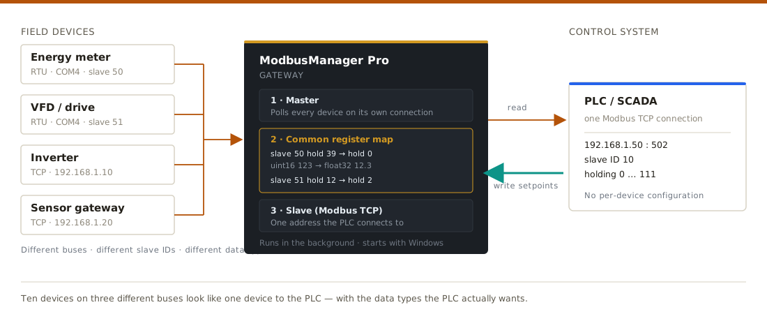
Diagram: Modbus RTU and TCP field devices are polled by ModbusManager Pro, which exposes one common register map that a PLC reads and writes over a single Modbus TCP connection
Role 1
Master — reads the devices
The gateway opens its own connection to every endpoint you define: serial ports and TCP addresses side by side. Each mapping row is polled at its own interval, and requests on the same connection are serialised so the bus is never flooded.
Role 2
Mapping — converts and merges
Every row says where a value comes from and where it lands: source slave ID, register type, address and data type on one side; common map slave ID, address and data type on the other. Scale and offset are applied on the way through, and reversed on the way back.
Role 3
Slave — serves the PLC
The common map is published as a Modbus TCP slave on a port you choose. The PLC connects to one IP, one port and one slave ID, and reads a contiguous block of registers. Writes into the map are forwarded to the original device.
// what the gateway does

Built for real installations

Everything below is configured in the Gateway tab — no scripting required.

🔀
Register aggregation
Pull any register from any device into any address of the common map. Group values logically — all fan speeds together, all setpoints in another block — regardless of where they physically live.
📐
Type and scale conversion
Source and common map each have their own data type: uint16, int16, uint32, int32, float32, coils and discrete inputs. Add scale and offset and the PLC receives engineering units instead of raw counts.
Write-through setpoints
When the PLC writes into the common map, the value is converted back and forwarded to the real device. 32-bit setpoints are assembled from both registers before being sent, so no half-written value ever reaches the device.
🔌
Mixed buses at once
Serial RTU ports and multiple Modbus TCP addresses run in parallel, each with its own connection and retry logic. One bad device or unplugged adapter does not stop the rest.
🖥
Runs in the background
Close the window and the gateway keeps polling from the tray. It can start with Windows and load its configuration automatically, so a commissioning laptop or panel PC comes back up on its own after a reboot.
📋
CSV import and diagnostics
Build large mappings in a spreadsheet and import them, or download the template to start from. Connection state, per-row errors and every forwarded write appear in the TX/RX log with automatic retry back-off.
// step by step

Setting up a gateway, start to finish

This walkthrough builds a working gateway from one RTU device and verifies it from the PLC side — using ModbusManager itself as the PLC, so you can test the whole chain without a PLC on the desk.

Step 1
Collect the details you need
For every device: the connection (serial port and baud rate, or IP address and port), the slave ID, and the register addresses you want, with their data types. If you already poll the device in ModbusManager, you have all of it. Disconnect the interactive connection before starting the gateway — one serial port can only have one owner, and the gateway will tell you if the port is already in use.
Step 2
Add a source endpoint
Open the Gateway tab and add an endpoint with + RTU or + TCP. RTU needs the COM port, baud rate and parity; TCP needs the host and port. Add as many as you like — a serial line and several IP addresses can run at the same time. Give each one a name you will recognise in the mapping table.
Gateway tab in ModbusManager Pro showing source endpoints: one Modbus RTU serial port and one Modbus TCP address
Source endpoints — serial and TCP side by side
Step 3
Map the registers
Add a row for every value. On the source side choose the endpoint, mode read, the device slave ID, register type, address and data type. On the common side choose the slave ID the PLC will use, the address, and the data type the PLC should see. Set scale if the device stores a scaled integer — a meter holding 123 for 12.3 needs scale 0.1 and common type float32.
Gateway mapping table showing source slave ID, register address and data type mapped to a common register map with scale and float32 conversion
One row per value — note uint16 → float32 with scale 0.1
Step 4
Set the PLC side and start
Choose the Slave TCP port the PLC will connect to — 502 is the Modbus standard, use another if something already occupies it. Tick Start gateway automatically if this machine should bring the gateway up on its own. Press Start gateway: the slave server starts, the endpoints connect, and the status pill turns green with connected under each endpoint.
Gateway running: green status indicator and connected source endpoint in ModbusManager Pro
Running, with the source endpoint connected
Step 5
Verify from the PLC side
You do not need a PLC to test this. Open a second connection in ModbusManager — Connection settings → TCP, host 127.0.0.1, the port you chose — and set the slave ID to the common map ID (not the device ID; this is the most common mistake). Read the addresses you mapped: the values from the field devices appear there, updating live.
Register view reading the common map over Modbus TCP on localhost, showing aggregated values from field devices
Reading the common map exactly as a PLC would
Step 6
Leave it running
For a machine that should keep the gateway alive, close the window to the tray instead of quitting, and enable Start with Windows from the tray menu. After a reboot the gateway loads its saved configuration and starts polling before anyone logs into the application. When a real PLC connects, point it at this computer's IP address, the slave port, and the common map slave ID.
Tray menu of ModbusManager Pro with options to keep running when the window is closed and to start with Windows
Tray menu — background operation and Windows autostart
// where it fits

Honest limits

Software on a PC is not the same thing as a DIN-rail gateway, and pretending otherwise wastes your time. Here is where each one belongs.

SituationModbusManager ProHardware gateway
Commissioning — proving the mapping works with real devices✓ IdealOverkill before the design is proven
Test bench, lab, temporary bridge during a retrofit✓ IdealUnnecessary cost
Small, non-critical system with a PC already on site✓ Works wellAlso fine
Panel PC or logging machine that stays powered✓ Background modeAlso fine
Permanent installation on a critical process✗ Use hardware✓ Watchdog, DIN rail, redundancy
Site with no PC and no Windows maintenance✗ Not suitable✓ The right tool
The practical use: prove the gateway design on real hardware during commissioning — mapping, scaling, write-through — before anyone orders a hardware gateway or writes the PLC blocks. If the installation is small and non-critical, the same setup can simply stay in service.
// frequently asked questions

Modbus gateway — FAQ

Can the gateway and my normal polling use the same COM port?+
No — a serial port can only be opened by one client at a time, and that is a Windows limitation, not a software one. The gateway owns the ports it uses while running. If you try to open the same port interactively you get a clear message telling you which port is in use, instead of a stream of access errors. Ethernet endpoints have no such restriction.
My device stores 123 and means 12.3. Can the PLC just read 12.3?+
Yes, and this is one of the main reasons to use the gateway. Set the source data type to uint16 with scale 0.1, and the common map data type to float32. The PLC reads a proper float. If the PLC writes a float setpoint back, the value is divided by the scale and written to the device as the integer it expects.
Do I have to keep the window open?+
No. The polling engine runs in a separate background process, so closing the browser view or the window does not interrupt it. Enable the tray option and the application stays resident; enable Windows autostart and it comes back after a reboot, loading the saved gateway configuration and starting on its own.
Which IP address and slave ID does the PLC use?+
The IP address is the address of the computer running ModbusManager — check it with ipconfig; the gateway listens on all network interfaces. The port is the Slave TCP port set in the Gateway tab, and the slave ID is the common slave ID from your mapping rows, not the ID of the field device. Remember to allow the port through the Windows firewall for connections from other machines.
What happens if a device is unplugged or stops answering?+
That endpoint reports the error in the log and retries with an increasing delay — two seconds, then four, up to thirty — so a missing device neither floods the log nor hammers the bus. Other endpoints keep working normally. When the device comes back, the gateway reconnects and logs that reads are succeeding again, without anyone pressing anything.
Can I build a large mapping without clicking every row?+
Yes. Download the CSV template from the Gateway tab, fill it in a spreadsheet — one row per value, with source and common columns — and import it. Existing rows are kept, so you can import in batches. Endpoint names in the CSV are matched to the endpoints you have defined.
Is this the same as an OPC server?+
No. An OPC server exposes data to OPC clients over OPC DA or UA. This gateway stays inside the Modbus world: Modbus in, Modbus out. That is deliberately narrower, and it is why a PLC that speaks nothing but Modbus TCP can use it with no extra software, drivers or licenses on either side.

Try the Modbus gateway free for 14 days

Download ModbusManager Pro, map your first devices into one register map, and read it from your PLC today. No credit card, no cloud, no subscription.

Download Pro trial See pricing

Windows 10/11 · 14-day trial · Pro from $119 one-time