Siemens S7-1200 / S7-1500 PUT/GET from a PC
Read and write a Siemens S7 PLC's data blocks, merkers, inputs and outputs from a Windows PC without writing any PLC code: two settings in TIA Portal, and ModbusManager Pro talks to the CPU over S7 communication (PUT/GET, port 102). Use it for an HMI dashboard, logging, alarms, or as a gateway between S7 and Modbus — in both directions.
PUT/GET or Modbus TCP?
There are two ways to get data out of an S7-1200 or S7-1500 into a PC program:
| PUT/GET (this page) | Modbus TCP (MB_SERVER) | |
|---|---|---|
| PLC program | None — two settings in the CPU and the DB | An MB_SERVER block and a register area mapped to your data |
| Addresses | The PLC's own: DB1.DBD4, M0.0, IW64 | Holding registers you assign |
| Data types | BOOL, BYTE, WORD, INT, DWORD, DINT, REAL, LREAL as declared | 16-bit registers you split and combine |
| Optimized DBs | Not accessible — turn optimization off | Accessible through the block you write |
| Best for | Reading an existing PLC without touching its program | A clean, documented interface you design |
For the Modbus route, see Modbus HMI for the S7-1200.
Setting Up the CPU in TIA Portal
1 Permit PUT/GET. Device configuration › select the CPU › Properties › Protection & Security › Connection mechanisms › tick Permit access with PUT/GET communication from remote partner.
2 Access level. Under Protection & Security, an access level that allows the access — Full access is simplest for commissioning. On an S7-1500 with a display, make sure the display does not demand a password for it.
3 Turn off optimized access on each DB you read. Right-click the data block › Properties › Attributes › untick Optimized block access. After a compile, the DB shows an Offset column — those offsets are the byte addresses you read.
4 Compile and download the hardware configuration and the changed blocks. No other program change is needed.
Connecting ModbusManager Pro
1 Add the PLC. Tags › Siemens S7… › + Add PLC: an ID (for example PLC1), the IP address, port 102, rack 0, slot 1 for an S7-1200/1500 (rack 0, slot 2 for an S7-300/400), and a poll interval.
2 Test read. Pick an area, DB, type and byte in the same dialog and press Read — a value means the CPU, the protection settings and the DB are right.
3 Make tags. Tags › + New Tag › type Siemens S7, choose the PLC and the address. Tags can be used everywhere a Modbus tag can: dashboard, trends, alarms, historian, scripts and the gateway.
4 Or bind an element directly. Any dashboard element can take Source = Siemens S7 with a PLC and an address; writable elements (setpoint, switch, slider, PID faceplate) write back to the PLC.
The ID ties tags to the PLC. A runtime package carries the ID, not the IP address, so each machine enters its own PLC's address once — one package fits every machine of a series.
Address Format
| Address | Means | Type |
|---|---|---|
| DB1,REAL4 | DB1, byte 4 (DB1.DBD4) | REAL |
| DB1,INT2 | DB1, byte 2 (DB1.DBW2) | INT |
| DB1,DINT8 / DB1,DWORD8 | DB1, bytes 8–11 | DINT / DWORD |
| DB1,X12.0 | DB1, byte 12, bit 0 (DB1.DBX12.0) | BOOL |
| DB2,LREAL16 | DB2, bytes 16–23 | LREAL |
| MW2 / MD4 / MR8 | Merker word / double word / REAL | WORD / DWORD / REAL |
| M0.0 | Merker bit | BOOL |
| IW64 / I0.1 | Input word / input bit (E works as I) | WORD / BOOL |
| QW64 / Q0.1 | Output word / output bit (A works as Q) | WORD / BOOL |
The address fields in the application compose these for you; short forms such as DB1,R4 or DB1,DI8 are understood too. A bit is written as true/false, integers are rounded, REAL and LREAL keep their fraction.
S7 ↔ Modbus Gateway
S7 to Modbus
In the Gateway tab, + Siemens S7 adds the PLC as a source. Each row maps an S7 address to a register in the gateway's Modbus map, so a SCADA, a BMS or another PLC reads the S7 data with plain Modbus TCP — and a write to that register goes on to the PLC.
The PLC reads and writes a DB in ModbusManager (S7 server)
The other way round: the gateway can act as an S7 server. Rows with destination S7 DB form virtual data blocks that the PLC reads with GET and writes with PUT — and the values behind them come from Modbus devices or tags. A PUT goes on to the row's device when its value changes. In TIA Portal: a GET/PUT connection to an unspecified partner at the PC's IP address (port 102), and absolute addresses such as P#DB100.DBX0.0 BYTE 16. A virtual DB is as long as its rows reach, in steps of 16 bytes.
Common Problems
- Every address reads BAD: PUT/GET is not permitted, or the protection level blocks it. Check step 1 and 2, and download.
- One DB reads BAD, the rest work: that DB is still optimized, or does not exist under that number.
- No connection at all: wrong IP or slot (1 for S7-1200/1500, 2 for S7-300/400), or port 102 blocked by a firewall.
- A value is nonsense: the byte offset is wrong — compare with the Offset column of the non-optimized DB, and check the type (REAL vs DINT on the same four bytes).
- The S7 server is not reachable from the PLC: port 102 is taken on the PC, or the PLC's IP is not in the allowed list.
Download a Ready-Made Workspace
- Eight S7 tags on PLC
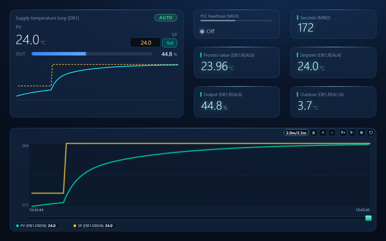
PLC1: a control loop in DB1 (process value, setpoint, output, auto bit, cycle counter, outdoor temperature), the heartbeat M0.0 and the seconds word MW2 - A dashboard: PID faceplate writing the setpoint and the auto/manual bit over PUT, heartbeat lamp, value cards and a PV/SP trend
PLC1 and your CPU's IP address (Tags › Siemens S7…), then open the workspace — the tags find it by ID. Change the DB numbers and offsets to your own data. Requires ModbusManager Pro.
Siemens_S7_PUT_GET.json
S7 PLC workspace: tags, PID faceplate and trend over PUT/GET. Open via Workspace › Open in ModbusManager Pro.
Try it with ModbusManager Pro
Siemens S7 and Modbus in one program: HMI, logging, alarms and gateway. Free 14-day trial. No credit card. Windows 10/11.
Frequently Asked Questions
Do I need to change the PLC program to use PUT/GET?
No. You permit PUT/GET in the CPU's protection settings, turn off optimized block access on the DBs you read, and download. No communication block is added to the program.
Can PUT/GET read optimized data blocks?
No. PUT/GET addresses data by absolute byte offset, which optimized DBs do not have. Turn off "Optimized block access" for each DB you want to read.
Does it work with the S7-300 and S7-400?
Yes, over the same S7 communication. Use rack 0 and slot 2 for an S7-300/400 instead of slot 1.
Can the PLC read data from ModbusManager?
Yes. The gateway's S7 server lets the PLC read virtual data blocks with GET and write them with PUT, with the values coming from Modbus devices or tags. Only PLC addresses on the allowed list can connect.
Is the Siemens S7 support finished?
It is released as beta in ModbusManager Pro 1.9.2 and later, tested against a simulated S7 PLC. Feedback from real CPUs is welcome.