ABB ACH580 Modbus RTU: Registers, Setup and Why It Won't Start
The ABB ACH580 HVAC drive has a Modbus RTU slave built in — the embedded fieldbus (EFB) on terminals 29–31. The register map is ABB's standard one, but the ACH580's HVAC defaults catch people out: the drive refuses to start until DI4 is closed, Actual value 2 reads zero until you configure it, and whether a lost BMS stops the fan depends on a parameter whose default changed between manual editions. This page covers the registers, the group 58 setup, the control word and those three traps, all from ABB's firmware manual.
Connection Settings (Parameter Group 58)
The EFB is Modbus RTU only on RS-485 (the same port also speaks BACnet MS/TP and N2; 58.01 picks one). For Modbus TCP you need an option module (FMBT-21 or FENA-21) or a gateway. Wire 29 B+, 30 A- and 31 DGND on X5; the termination (S4) and bias (S5) switches are next to it — on only at the ends of the line.
| Parameter | Set to | Default / note |
|---|---|---|
| 58.01 Protocol enable | Modbus RTU | Off until you choose it |
| 58.03 Node address | 1–247 | 1 |
| 58.04 Baud rate | as the master | 19.2 kbps |
| 58.05 Parity | as the master | 8 EVEN 1 |
| 58.14 Communication loss action | Fault (or Speed ref safe) | No action in Rev J — see below |
| 58.15 Communication loss mode | — | Cw / Ref1 / Ref2: only writes reset the timer |
| 58.16 Communication loss time | — | 30.0 s |
| 58.25 Control profile | ABB Drives | ABB Drives (DCU Profile also possible) |
| 58.33 Addressing mode | Mode 0 | Mode 0 |
| 58.34 Word order | — | LO-HI (low word first) |
| 20.01 Ext1 commands | Embedded fieldbus | start / stop from Modbus |
| 28.11 Ext1 frequency ref1 | EFB ref1 | scalar control (the ACH580 default); 22.11 in vector |
| 58.06 Communication control | Refresh settings | group 58 changes take effect only after this or a reboot |
| 96.07 Parameter save manually | Save | keeps the values after power-off |
58.06 = Refresh settings or a power cycle. After power-up there is also a 30-second delay before the communication-loss supervision starts.
Holding Register Map
All registers are holding registers: read with FC03, written with FC06 or FC16. ABB numbers them 400001…; on the wire the address is that number minus 400001.
| ABB register | Wire | Default content | Selected by |
|---|---|---|---|
| 400001 | 0 | Control word (CW 16bit) | 58.101 |
| 400002 | 1 | Reference 1 (Ref1 16bit) | 58.102 |
| 400003 | 2 | Reference 2 (Ref2 16bit) | 58.103 |
| 400004 | 3 | Status word (SW 16bit) | 58.104 |
| 400005 | 4 | Actual value 1 (Act1 16bit) | 58.105 |
| 400006 | 5 | Actual value 2 (Act2 16bit) — 0 by default | 58.106 |
| 400007–400014 | 6–13 | Data I/O 7–14, None (read 0) until set | 58.107–58.114 |
| 400090–400095 | 89–94 | Error registers of the last query | — |
| 400101… | 100… | Any parameter, by 58.33 (next section) | — |
Scaling of the references and actual values
The ACH580 ships in scalar motor control (99.04), so with the default type Speed or frequency both Ref1 and Act1 are a frequency: 20000 = 46.02 Frequency scaling, which is 50.00 Hz or 60.00 Hz depending on the drive's 50/60 Hz setting. Act1 = 17966 on a 50 Hz drive is 17966 × 50 / 20000 = 44.9 Hz. In vector control they become speed, with 20000 = 46.01. Negative values (two's complement) mean reverse.
Reading Any Parameter Directly
With 58.33 Addressing mode at its default Mode 0 every parameter has two addresses, so you do not have to map anything into Data I/O first:
- 16-bit: 400000 + 100 × group + index — 01.06 is 400106 (wire 105). Scaled by the 16-bit fieldbus equivalent: for 01.06 that is 46.02 again, for 01.07 it is 46.05 (default 10000 A = 10000, i.e. whole amps).
- 32-bit: 420000 + 200 × group + 2 × index — 01.06 is 420212 (wire 20211), two registers, low word first (58.34 LO-HI). The 32-bit scaling is fixed and finer: 100 = 1 Hz, 100 = 1 A.
| Parameter | 32-bit register | Wire | Scale (FbEq32) |
|---|---|---|---|
| 01.06 Output frequency | 420212 | 20211 | ÷ 100 → Hz |
| 01.07 Motor current | 420214 | 20213 | ÷ 100 → A |
| 01.10 Motor torque | 420220 | 20219 | ÷ 10 → % |
| 01.11 DC voltage | 420222 | 20221 | ÷ 100 → V |
| 01.13 Output voltage | 420226 | 20225 | V |
| 01.14 Output power | 420228 | 20227 | ÷ 100 → kW |
| 05.11 Inverter temperature | 421022 | 21021 | ÷ 10 → % of fault limit |
| Parameter | 16-bit register | Wire | Content |
|---|---|---|---|
| 04.01 Tripping fault | 400401 | 400 | Fault code (hex in the manual: 6681 = 0x6681) |
| 04.06 Active warning 1 | 400406 | 405 | Warning code, e.g. 0xAFEE |
| 10.02 DI delayed status | 401002 | 1001 | Bits 0–5 = DI1–DI6 |
Control Word: Start, Stop, Reset
ABB Drives profile, register 400001 (wire 0). Bit 10 REMOTE_CMD must be 1 for the drive to take commands from Modbus, which is why every value below has 0x400 in it. ABB's sequence for the ACH580:
| Step | Write to 400001 | Result |
|---|---|---|
| Start 1 | 1142 (0x0476) | NOT READY TO SWITCH ON |
| Start 2 | 1150 (0x047E) | READY TO SWITCH ON (stopped) — once SW bit 0 = 1 |
| Start 3 | 1151 (0x047F) | OPERATION (running) with the reference in 400002 |
| Stop | 1143 (0x0477) | Stop by 21.03 Stop mode — ABB's preferred stop |
| Ramp stop | 1150 (0x047E) | OFF1 ramp stop (cannot be interrupted) |
| Coast stop | 1149 (0x047D) | OFF2 emergency coast |
| Emergency ramp | 1147 (0x047B) | OFF3 emergency ramp stop |
| Fault reset | rising edge of bit 7 | e.g. 0x04F6, then back to 0x0476 |
The status word at 400004 (wire 3) answers: bit 0 ready to switch on, 1 ready to run, 2 running, 3 fault, 7 warning, 8 at setpoint, 9 remote. A running drive at speed under Modbus control reads 0x0337. The same bits are also readable one by one as discrete inputs (FC02, 100001…) and the control word bits as coils (FC01/FC05, 000001…); the digital inputs DI1–DI6 follow at 100033–100038.
Why the ACH580 Won't Start from Modbus
The control word is right, the status word says ready, and nothing turns. On an ACH580 it is usually one of these, in this order:
- Warning AFEE Start interlock 1. In the HVAC default configuration 20.41 Start interlock 1 is wired to DI4 (damper end switch, safety chain). With DI4 open the drive will not start, whatever Modbus says. Read 10.02 bit 3 or warning 04.06 = 0xAFEE. Close DI4 or set 20.41 to Not used if there is no interlock.
- Warning AFED Run permissive. 20.40 has a source that is off. Not used by default, but often set at commissioning.
- Panel in Hand or Off. Local control from the panel always overrides the external location. Status word bit 9 (remote) is 0. Press Auto.
- 20.01 is not Embedded fieldbus, or the reference source (28.11, or 22.11 in vector) is not EFB ref1 — the drive starts but runs to the wrong reference.
- Bit 10 REMOTE_CMD missing: writing 0x0007 or 0x000F instead of 0x0477 / 0x047F.
- Safe torque off open on X4 — both channels must be closed for any start.
Communication Loss: Check 58.14 on Your Drive
The current firmware manual (3AXD50000027537 Rev J, 2026) lists 58.14 Communication loss action = No action as the default: if the master stops, the drive keeps running on the last command. Older editions of the same manual list Fault, so read 58.14 on the panel rather than trusting either. When it is Fault, the drive trips with 6681 EFB comm loss after 58.16 (30 s) — but only when control or the reference is expected from the EFB. Other choices: Last speed, Speed ref safe (22.41 / 28.41), Fault always, Warning (A7CE).
Mind 58.15: with the default Cw / Ref1 / Ref2 only a write of the control word or a reference resets the timer. A BMS that starts the fan once and then only reads will, with 58.14 = Fault, trip the drive 30 s later. Write the control word cyclically (ModbusManager's periodic write does this), or set 58.15 to Any message.
Diagnostics Built into the EFB
- Error registers 400090–400095 describe the last failed query: 400091 the function code, 400092 the error (02h value out of limits, 03h faulty index, 05h wrong data type), 400093 the register that failed, 400094 / 400095 the last good write and read. Write 1 to 400090 to clear them.
- FC 2Bh / 0Eh Read Device Identification returns vendor "ABB", the product code and product name "ACH580" — a quick way to confirm what is on the address.
- 58.08–58.12 on the panel count received and transmitted packets, UART errors and CRC errors; a rising CRC count means wiring or termination, not addressing.
Common Mistakes
- Everything is one register off: 400001 was requested as address 1. The control word is wire address 0, the status word 3.
- Frequency reads 17966 instead of 44.9: Ref1 / Act1 are in 20000 = 46.02 units, not Hz × 10.
- Act2 is always 0: the default (Transparent, Not selected). Configure 58.29 / 58.32 or read 01.07 directly.
- 32-bit values are huge: combined high word first. The ACH580 sends the low word first (58.34 LO-HI).
- Exception 02 on a block that "should" exist: it crosses a parameter index that does not exist.
- Group 58 edits ignored: no 58.06 Refresh settings and no reboot.
- The fan stops 30 s after the BMS starts it: 58.14 = Fault and the BMS only reads (58.15 Cw / Ref1 / Ref2).
Step-by-Step: Reading an ACH580 with ModbusManager
- Wire a USB–RS-485 adapter to X5: 29 B+, 30 A-, 31 DGND. Termination on at the adapter end and at the last drive.
- Set 58.01 Modbus RTU, 58.03 the address, then 58.06 Refresh settings. Keep 19.2 kbps, 8 EVEN 1 unless the line uses something else.
- In ModbusManager choose RTU, the COM port, 19200 baud, Even parity, 1 stop bit.
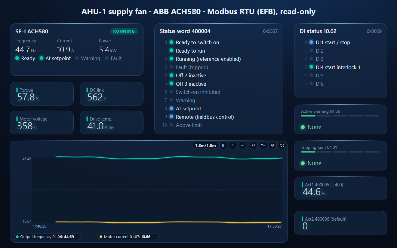
- Poll FC03 from address 0, quantity 6. The status word (address 3) should show bit 0 (ready to switch on) and bit 9 (remote) once 20.01 is Embedded fieldbus and the panel is in Auto; it reads 0x0337 when the drive runs at setpoint.
- Open the workspace below to get the parameters, DI4 and the warning and fault codes as named, scaled values on a dashboard.
Download a Ready-Made Workspace
- Seven FC03 polls: status word and actual values (400001–400006), the 32-bit parameters 01.06–01.11, 01.13–01.14 and 05.11, DI status 10.02, tripping fault 04.01 and active warning 04.06
- 14 register tags with the wire address, Int32 low word first and the scale already set
- A dashboard: drive faceplate, ABB Drives status word bits, DI1–DI6 with the DI4 start interlock, warning and fault codes as text (AFEE, AFED, A7CE, 6681…), torque, DC link, motor voltage, drive temperature, Act1 / Act2 as they arrive (Act2 = 0 by default) and a frequency and current trend
ABB_ACH580_Modbus_monitor.json
ABB ACH580 read-only monitor workspace. Open via Workspace › Open in ModbusManager Pro.
Try it with ModbusManager Pro
Faceplate, status bits, historian and alarms for your drives. Free 14-day trial. No credit card. Windows 10/11.
On BACnet instead? The ACH580 BACnet points list covers the same drive over MS/TP. For the general-purpose sibling see the ACS580 Modbus guide, and for references and scaling across brands the VFD speed reference guide.
Frequently Asked Questions
What is the Modbus address of the ACH580 status word?
Holding register 400004, which is address 3 on the wire (FC03). The control word is 400001 (address 0), the frequency reference 400002 (address 1) and Actual value 1 400005 (address 4).
Does the ACH580 support Modbus TCP?
Not on its own: the embedded fieldbus is Modbus RTU on RS-485. Modbus TCP needs an FMBT-21 or FENA-21 option module, or an RTU-to-TCP gateway.
Why does Actual value 2 always read 0?
By default 58.29 EFB act2 type is Transparent and 58.32 EFB act2 transparent source is Not selected, so register 400006 carries nothing. Set a source or read the parameter directly, e.g. 01.07 Motor current at 420214.
Why won't my ACH580 start over Modbus?
Most often the start interlock: in the HVAC default 20.41 Start interlock 1 is DI4, and with DI4 open the drive shows warning AFEE and does not start. Also check the panel is in Auto, 20.01 is Embedded fieldbus and bit 10 of the control word is set (0x047F, not 0x000F).
How is the ACH580 frequency scaled on Modbus?
Reference 1 and Actual value 1 use 20000 = 46.02 Frequency scaling (50 or 60 Hz) in the default scalar control. Read 01.06 at 420212 in 32-bit instead and the value is simply Hz × 100.
Sources
ABB, ACH580 HVAC control program firmware manual, 3AXD50000027537 Rev J (2026-02-23): chapter "Modbus RTU control through the embedded fieldbus interface (EFB)" (pp. 287–313), parameter groups 01, 04, 05, 10, 20, 46, 58 and 99 (pp. 397–405, 477, 620–625), the additional parameter data (pp. 735–748) and the HVAC default I/O. Public download from the ABB library. The 58.14 default of Fault comes from the earlier Rev C (2017). Check the manual for your firmware version; the workspace was tested against a simulator built from this manual, not a physical drive.