Omron E5CC Modbus RTU: Switch from CompoWay/F, Two Address Maps, No Decimal Point
Omron's E5CC and E5EC (the E5□C family) temperature controllers have RS-485 and speak Modbus RTU — but not out of the box. They ship set to Omron's own CompoWay/F protocol, they hold every value in two address maps at once, and they send integers with the decimal point left out. This guide covers the switch, the registers a dashboard needs, and how to read the status bits, including the one that says 1 when the controller is stopped.
Switch the Protocol to Modbus
In the communications setting level (hold the O key 3 s for the initial setting level, then press it under 1 s), set:
| Parameter | Factory | For Modbus |
|---|---|---|
| PSEL | CompoWay/F (cwf) | Modbus (mod) |
| U-NO | 1 | slave address 1–99 |
| BPS | 9.6 | 9600 / 19200 / 38400 / 57600 |
| PRTY | even | even or odd with 1 stop bit, or none with 2 stop bits (8 data bits) |
| SDWT | 20 ms | send data wait time |
Then reset the controller — Omron's manual: new communications settings are enabled by resetting. Until then it still answers in CompoWay/F and a Modbus master sees nothing.
Two Maps for the Same Values
- 4-byte mode, from 0x0000: each value is two registers, high word first, at an even address — read an even number of registers from an even address. PV 105.0 °C is 0000 041A.
- 2-byte mode, from 0x2000: each value is one register. The same PV is 041A at 0x2000.
Omron's own example: PV in 4-byte mode 01 03 00 00 00 02, in 2-byte mode 01 03 20 00 00 01 → 03E8 = 100.0 °C. Addresses are hex, sent as they are. Function codes 03 read, 06 write single / operation command, 16 write multiple, 08 echoback — no FC04, no coils. At most 106 registers per read.
No Decimal Point on the Wire
Values are integers “ignoring the decimal point position”: 150.0 °C reads as 1500. How many digits are after the point depends on the input type and setting, and the controller says it: Decimal Point Monitor at 0x0420 / 0x2410 (0–3). Divide by 10 to that power. Negative values are two's complement.
Key Registers
| 4-byte | 2-byte | Value | Unit |
|---|---|---|---|
| 0x0000 | 0x2000 | Process value | ÷ 10dp |
| 0x0002 | 0x2001 | Status (2-byte: low 16 bits) | bits |
| 0x0004 | 0x2002 | Internal set point | ÷ 10dp |
| 0x0006 | 0x2003 | Heater current 1 | 0.1 A |
| 0x0008 | 0x2004 | MV heating (−5.0…105.0) | 0.1 % |
| 0x000A | 0x2005 | MV cooling | 0.1 % |
| 0x0106 | 0x2103 | Set point (read / write) | ÷ 10dp |
| 0x0108 | 0x2104 | Alarm value 1 | ÷ 10dp |
| 0x040C | 0x2406 | Status, low 16 bits | bits |
| 0x040E | 0x2407 | Status, high 16 bits | bits |
| 0x0420 | 0x2410 | Decimal Point Monitor | 0–3 |
Status Bits
| Bit | Meaning | Bit | Meaning |
|---|---|---|---|
| 6 | Input error | 20 | Write mode (1 = RAM) |
| 8 / 9 | Control output heating / cooling | 23 | AT running |
| 10 / 11 | Heater burnout CT1 / CT2 | 24 | RUN/STOP: 1 = STOP |
| 12 / 13 / 14 | Alarm 1 / 2 / 3 | 25 | Communications writing (1 = on) |
| 2 | A/D converter error | 26 | Auto / manual (1 = manual) |
In 2-byte mode bits 16–31 are in the second status register (0x2407): bit 24 is its bit 8.
Writing: Communications Writing First
Every write is refused with exception 04 until Communications Writing is on: FC06 to address 0x0000 with 00 01. Operation commands go to the same address, command code in the high byte: 01 00 RUN / 01 01 STOP, 03 01 start AT, 09 01 manual. Writes go to non-volatile memory, which has a limited number of write cycles — for a set point written often, switch to RAM write mode (04 01).
Common Mistakes
- No answer: the protocol is still CompoWay/F, or the controller was not reset after the change.
- Exception 03 at 0x0000: one register read in 4-byte mode, or an odd address — read two, or use 0x2000.
- Temperature 1500 °C: the decimal point not applied (Decimal Point Monitor).
- A “running” lamp that is on when stopped: bit 24 is 1 = STOP.
- Exception 04 on every write: Communications Writing off, the setup area, a protect level, or AT running.
Step-by-Step: Reading an E5CC with ModbusManager
- Set PSEL to Modbus, the address and the baud rate, and reset the controller.
- In ModbusManager choose RTU, the baud rate, even parity, 1 stop bit, the unit number.
- Read FC03 from 0x2000, quantity 6: PV, status, internal SP, heater current, MV.
- Read 0x2410 for the decimal point, and divide. Or open the workspace below.
Download a Ready-Made Workspace
- Four FC03 polls in the 2-byte map: 0x2000–0x2005, set point and alarm 1 at 0x2103, status 0x2406–0x2407, Decimal Point Monitor 0x2410
- 9 register tags with one decimal applied, and a script that takes RUN/STOP, manual, alarm 1 and input error out of the status words
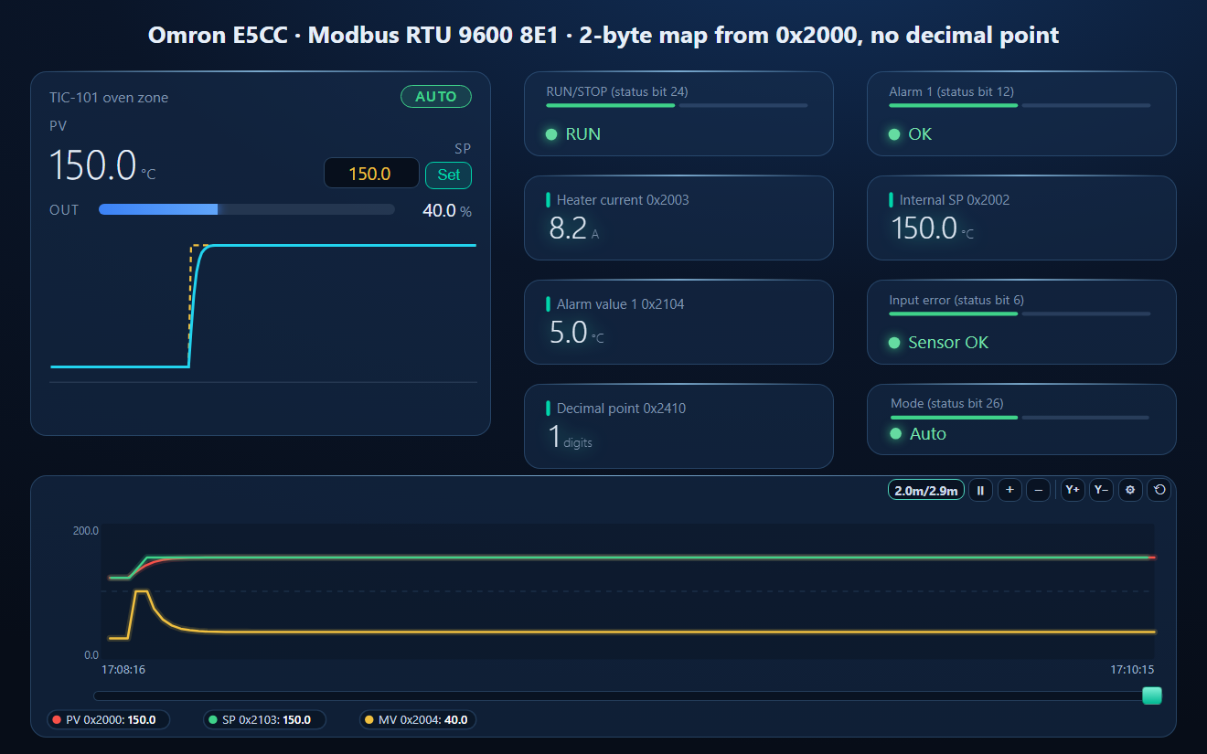
- A dashboard: the PID loop faceplate (PV, SP, output, auto / manual), RUN/STOP, alarm 1, heater current, internal set point, alarm value, input error, decimal point and mode, and a PV / SP / MV trend
Omron_E5CC.json
Omron E5CC temperature controller workspace (Modbus RTU). Open via Workspace › Open in ModbusManager Pro, or from the in-app Device library.
Try it with ModbusManager Pro
PID loop faceplate, alarms on the status bits, historian for PV and MV, and MQTT to Home Assistant. Free 14-day trial. No credit card. Windows 10/11.
A PLC beside the controllers: Siemens S7 over PUT/GET. Scripts that turn status words into flags: Tags and Structured Text. All guides: Modbus device guides.
Frequently Asked Questions
How do I enable Modbus on an Omron E5CC?
In the communications setting level set PSEL from CompoWay/F to Modbus, set the unit number, baud rate and parity, then reset the controller. The factory protocol is CompoWay/F, and new communications settings take effect only after a reset.
Why does the E5CC answer exception 03 at address 0?
Address 0x0000 is the 4-byte map: each value is two registers and must be read from an even address with an even count. Read two registers there, or read one register at 0x2000 in the 2-byte map.
Why does my E5CC temperature read 1500?
The E5CC sends integers without the decimal point. The Decimal Point Monitor (0x2410 in 2-byte mode) says how many digits follow the point: with 1, 1500 is 150.0 °C.
How do I write the set point of an E5CC over Modbus?
First turn on Communications Writing with FC06 to address 0x0000, value 0x0001. Then write the set point at 0x2103 (or 0x0106 in 4-byte mode), without the decimal point. Use RAM write mode for frequent writes.
Which bit shows whether the E5CC is running?
Status bit 24, RUN/STOP — 1 means STOP. In the 2-byte map it is bit 8 of 0x2407.
Sources
Omron, E5□C Digital Temperature Controllers Communications Manual, Cat. No. H175-E1-17 (September 2022), files.omron.eu. Tested against a simulator built from this manual, not against a physical controller.