Siemens SINAMICS G120 Modbus RTU: Register Map, STW1 and ZSW1
A SINAMICS G120 with a CU240B-2 or CU240E-2 control unit is a Modbus RTU slave once you choose it in p2030 — and Siemens gives it a fixed register map: control and status words at 40100 and 40110, speed, frequency, current and power from 40340, fault numbers from 40400. This page covers which control units have Modbus at all, the setup parameters, the map with its scaling, and the STW1 / ZSW1 bits, from Siemens's operating instructions and fieldbus function manual.
Which Control Units Have Modbus
| Control Unit | Article number | Fieldbus |
|---|---|---|
| CU240B-2 | 6SL3244-0BB00-1BA1 | USS, Modbus RTU |
| CU240E-2 | 6SL3244-0BB12-1BA1 | USS, Modbus RTU |
| CU240E-2 F | 6SL3244-0BB13-1BA1 | USS, Modbus RTU |
| … DP / DP-F | …-1PA1 | PROFIBUS DP only |
| … PN / PN-F | …-1FA0 | PROFINET, EtherNet/IP |
Only the RS-485 variants ending in -1BA1 speak Modbus RTU. A DP or PN control unit cannot be switched to Modbus by any parameter — check the article number before planning the wiring.
Setup Parameters
| Parameter | Set to | Factory setting / note |
|---|---|---|
| p2030 | 2 = Modbus RTU | Fieldbus protocol selection |
| p2020 | baud rate code | 7 = 19200 (5 = 4800, 6 = 9600, 8 = 38400 … 13 = 187500) |
| p2021 | 1–247 | 1 — only used when the address switch on the control unit is 0 |
| p2031 | parity | 2 = even (0 = none, 1 = odd) |
| p2040 | monitoring time | 10 s for Modbus (0 = off) |
| p2024 | times | [0] max. telegram processing time 1000 ms |
| r2029 | — | error statistics: good, rejected, framing, overrun, parity, CRC, length |
The address switch on the control unit wins over p2021. A new address or protocol applies after the power is switched off and on. If no process data arrive within p2040 the drive faults; the timeout counts only the process-data registers (40100, 40101, 40110, 40111).
Register Map
FC03 reads, FC06 / FC16 write. On the wire the address is the register minus 40001: Siemens's own example reads 40110 with start address 006D hex = 109. A register outside the map is answered with an exception.
| Register | Wire | Content | Scale |
|---|---|---|---|
| 40100 | 99 | STW1 control word (R/W) | bits |
| 40101 | 100 | Main setpoint (R/W) | 4000 hex = 100 % of p2000 |
| 40110 | 109 | ZSW1 status word | bits |
| 40111 | 110 | Main actual value | 4000 hex = 100 % of p2000 |
| 40324 | 323 | Reference speed p2000 | rpm |
| 40340 / 40341 | 339 / 340 | Speed setpoint r0020 / speed actual r0022 | rpm |
| 40342 | 341 | Output frequency r0024 | ÷ 100 → Hz |
| 40343 / 40344 | 342 / 343 | Output voltage r0025 / DC link r0026 | V |
| 40345 | 344 | Current actual r0027 | ÷ 100 → A |
| 40346 | 345 | Torque r0031 | ÷ 100 → Nm |
| 40347 | 346 | Active power r0032 | ÷ 100 → kW |
| 40348 | 347 | Energy r0039 | kWh |
| 40349 | 348 | Control: manual / auto r0807 | 0 / 1 |
| 40400… | 399… | Fault numbers r0947[0]… | — |
| 40240–40245 | 239–244 | Digital inputs DI 0–5 | 0 / 1 |
| 40260–40263 | 259–262 | Analog inputs AI 0–3 | ÷ 100 → % |
Any other parameter is reached acyclically through data set 47 in registers 40601–40722 (40601 control, 40602 = 47 and length, data from 40603).
STW1 and ZSW1
STW1 (40100): bit 0 ON / OFF1, 1 no OFF2 (coast), 2 no OFF3 (quick stop), 3 enable operation, 4–6 ramp generator and setpoint enable, 7 acknowledge fault on 0→1, 10 control via PLC (0 = the drive ignores the Modbus process data), 11 reverse, 13 / 14 motorized potentiometer up / down. Bits 1–6 and 10 set with bit 0 = 0 gives 0x047E (ready); setting bit 0 gives 0x047F and the motor runs to the setpoint in 40101.
| ZSW1 bit | 1 means | bit | 1 means |
|---|---|---|---|
| 0 | Ready for switching on | 8 | Speed deviation within tolerance |
| 1 | Ready | 9 | Master control requested |
| 2 | Operation enabled | 10 | Comparison speed reached |
| 3 | Fault active | 11 | Current / torque limit reached |
| 4 / 5 | OFF2 / OFF3 inactive | 13 | No motor overtemperature alarm |
| 6 | Switching on inhibited | 14 | Motor rotates clockwise |
| 7 | Alarm active | 15 | Depends on telegram (CDS / no inverter overload alarm) |
Switching on inhibited (bit 6) after a power-up means the drive needs an OFF1 first: write 0x047E, then 0x047F.
Common Mistakes
- No answer at all: a DP or PN control unit, or p2030 not 2, or no power cycle since.
- Answers on the wrong address: the address switch is not 0, so p2021 is ignored.
- Everything one register off: 40110 requested as 110; on the wire it is 109.
- Commands ignored: STW1 bit 10 (control via PLC) is 0, or the drive is in manual (40349 = 0).
- Drive faults after 10 s: p2040 monitoring; poll the process data registers continuously.
- Frequency 3970 instead of 39.7: 40342 is Hz × 100.
Step-by-Step: Reading a G120 with ModbusManager
- Check the control unit is a -1BA1 type; set the address switch to 0.
- Set p2030 = 2, p2021 = address, p2020 and p2031 as on the line; power off and on.
- In ModbusManager choose RTU, 19200, Even, 1 stop bit.
- Read FC03 address 109, quantity 2: ZSW1 and the actual value.
- Open the workspace below.
Download a Ready-Made Workspace
- Four FC03 polls: 40110–40111, the diagnostics 40340–40349, faults 40400–40403 and p2000
- 14 tags with the wire address and scaling set
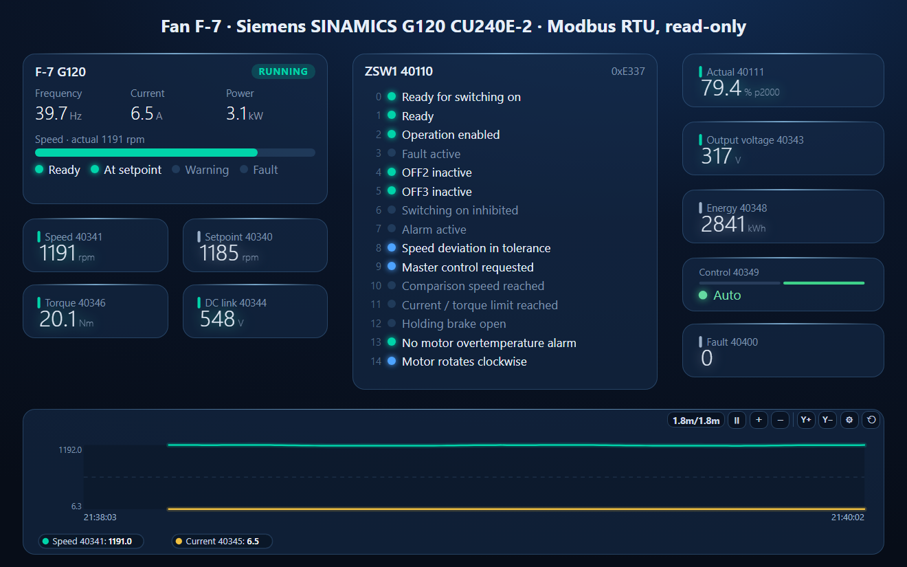
- A dashboard: drive faceplate, ZSW1 bit by bit, speed, setpoint, torque, DC link, actual value, voltage, energy, manual / auto, fault number and a trend
Siemens_G120_monitor.json
Siemens SINAMICS G120 read-only workspace. Open via Workspace › Open in ModbusManager Pro.
Try it with ModbusManager Pro
Drive faceplate, status bits, historian and alarms — and S7 PLCs over PUT/GET. Free 14-day trial. No credit card. Windows 10/11.
The PLC on the same panel: S7-1200 / S7-1500 over PUT/GET. Other drives: Altivar ATV320, Danfoss FC 102, ABB ACH580.
Frequently Asked Questions
Which SINAMICS G120 control units support Modbus RTU?
The RS-485 variants: CU240B-2 (6SL3244-0BB00-1BA1), CU240E-2 (6SL3244-0BB12-1BA1) and CU240E-2 F (6SL3244-0BB13-1BA1). The DP and PN variants do not.
What are the G120 Modbus registers for control and status word?
40100 is control word STW1 and 40101 the main setpoint; 40110 is status word ZSW1 and 40111 the main actual value. On the wire subtract 40001: ZSW1 is address 109.
How do I set the Modbus address on a G120?
Set p2030 = 2 (Modbus RTU) and p2021 to the address, with the control unit's address switch at 0 — otherwise the switch wins. Power the drive off and on.
How is the G120 setpoint scaled on Modbus?
40101 and 40111 use 4000 hex (16384) = 100 % of the reference speed p2000, which you can read at 40324. Speed in rpm is also at 40341 directly.
Why does the G120 ignore my Modbus commands?
STW1 bit 10 (control via PLC) must be 1, the drive must not be in manual (40349), and after power-up an OFF1 is needed first: 0x047E, then 0x047F.
Sources
Siemens, Converter with the CU240B-2 and CU240E-2 Control Units, Operating Instructions 04/2018, FW V4.7 SP10, A5E34259001B; SINAMICS G120 Fieldbus Function Manual 11/2020, FW V4.7 SP13, A5E34229197C (the edition on Siemens's download server is in Chinese; register numbers and parameter names are the same). Tested against a simulator built from these documents, not a physical drive.