Danfoss VLT FC 102 / FC 302 Modbus RTU: Registers and Scaling
Danfoss VLT drives speak Modbus RTU on their built-in RS-485 port, but only once you select it: the same port also runs Danfoss's own FC protocol, every parameter sits at ten times its number, and every value is an integer you have to scale by the parameter's conversion index. This page covers the setup, the control and status words, how to read any parameter and how to scale it — from Danfoss's FC 102 design and programming guides, with the FC 302 checked against its own programming guide.
Setting Up the RS-485 Port
| Parameter | Set to | Note |
|---|---|---|
| 8-30 Protocol | Modbus RTU | The other choices include Danfoss's FC protocol. The change applies only after a power cycle. |
| 8-31 Address | 1–247 | The range depends on the protocol chosen in 8-30 |
| 8-32 Baud Rate | 2400–115200 | Default depends on 8-30 |
| 8-33 Parity / Stop Bits | Even, 1 stop bit | The Modbus default |
| 8-35 / 8-36 | — | Minimum / maximum response delay |
| 8-03 / 8-04 | Timeout time / function | 8-04 is Off by default: a lost master does not stop the drive |
Terminals 68 (+) and 69 (−) on the control card; switch S801 (BUS TER.) switches on the termination at the end of the line. To run the motor from Modbus, the control word must be accepted: 8-50 to 8-56 decide how its bits combine with the digital inputs, and bit 10 of the control word itself must be 1.
Register = 10 × Parameter Number
Danfoss maps every parameter into the holding registers: parameter P (group × 100 + index) is register 10 × P. Danfoss's own example reads 3-03 Maximum Reference, "register 03030", at address 0BD5 = 3029: on the wire it is one less, as with any 4xxxx register. So:
| Parameter | Register | Wire | Type | Scale |
|---|---|---|---|---|
| 16-13 Frequency | 16130 | 16129 | Uint16 | ÷ 10 → Hz |
| 16-14 Motor Current | 16140 | 16139 | Int32 | ÷ 100 → A |
| 16-10 Power [kW] | 16100 | 16099 | Int32 | × 10 W (÷ 100 → kW) |
| 16-12 Motor Voltage | 16120 | 16119 | Uint16 | ÷ 10 → V |
| 16-30 DC Link Voltage | 16300 | 16299 | Uint16 | V |
| 16-34 Heatsink Temp. | 16340 | 16339 | Uint8 | °C |
| 16-03 Status Word | 16030 | 16029 | V2 | bits |
| 16-90 / 16-92 Alarm / Warning Word | 16900 / 16920 | 16899 / 16919 | Uint32 | bits |
Conversion index: parameters travel as whole numbers, and each one's index in the programming guide says where the decimal point is: −1 means divide by 10, −2 by 100, +1 multiply by 10. 16-10 is the odd one — index 1 in watts, so the bus value counts in 10 W steps. 32-bit values take two registers, high word first: Danfoss's example returns 0016 E360 = 1 500 000 for 1500 rpm.
Control and Status Words
| Register | Wire | Content | Direction |
|---|---|---|---|
| 50000 | 49999 | CTW, control word | master → drive |
| 50010 | 50009 | REF, bus reference | master → drive |
| 50200 | 50199 | STW, status word | drive → master |
| 50210 | 50209 | MAV, main actual value | drive → master |
The same words are also coils 1–16 (CTW), 17–32 (REF), 33–48 (STW) and 49–64 (output frequency). REF and MAV are percent: 16384 (0x4000) = 100 %, negative in two's complement. Coil 65 decides whether parameter writes go to RAM only (0) or also to EEPROM (1).
Control word, FC profile
Most bits are "1 = keep running": 02 = 0 is a DC brake, 03 = 0 coasts, 04 = 0 is a quick stop, 05 = 0 freezes the output, 06 = 1 starts and 0 ramps down, 07 resets on a 0→1 edge, 10 = 1 marks the word as valid. A run command therefore sets bits 2–6 and 10: 0x047C; clearing bit 6 (0x043C) ramps to stop. Bits 13/14 select the set-up, 15 reverses, 11/12 drive relays 01 and 04 when 5-40 is set to the control word bits.
Status word, FC profile
| Bit | 1 means | Bit | 1 means |
|---|---|---|---|
| 0 | Control ready | 8 | Speed = reference |
| 1 | Drive ready | 9 | Bus control (0 = local) |
| 2 | Enable (not coasting) | 10 | Frequency limit OK |
| 3 | Trip | 11 | In operation |
| 4 | Error, no trip | 12 | Stopped, auto start |
| 6 | Triplock | 13 / 14 / 15 | Voltage / torque / timer exceeded |
| 7 | Warning |
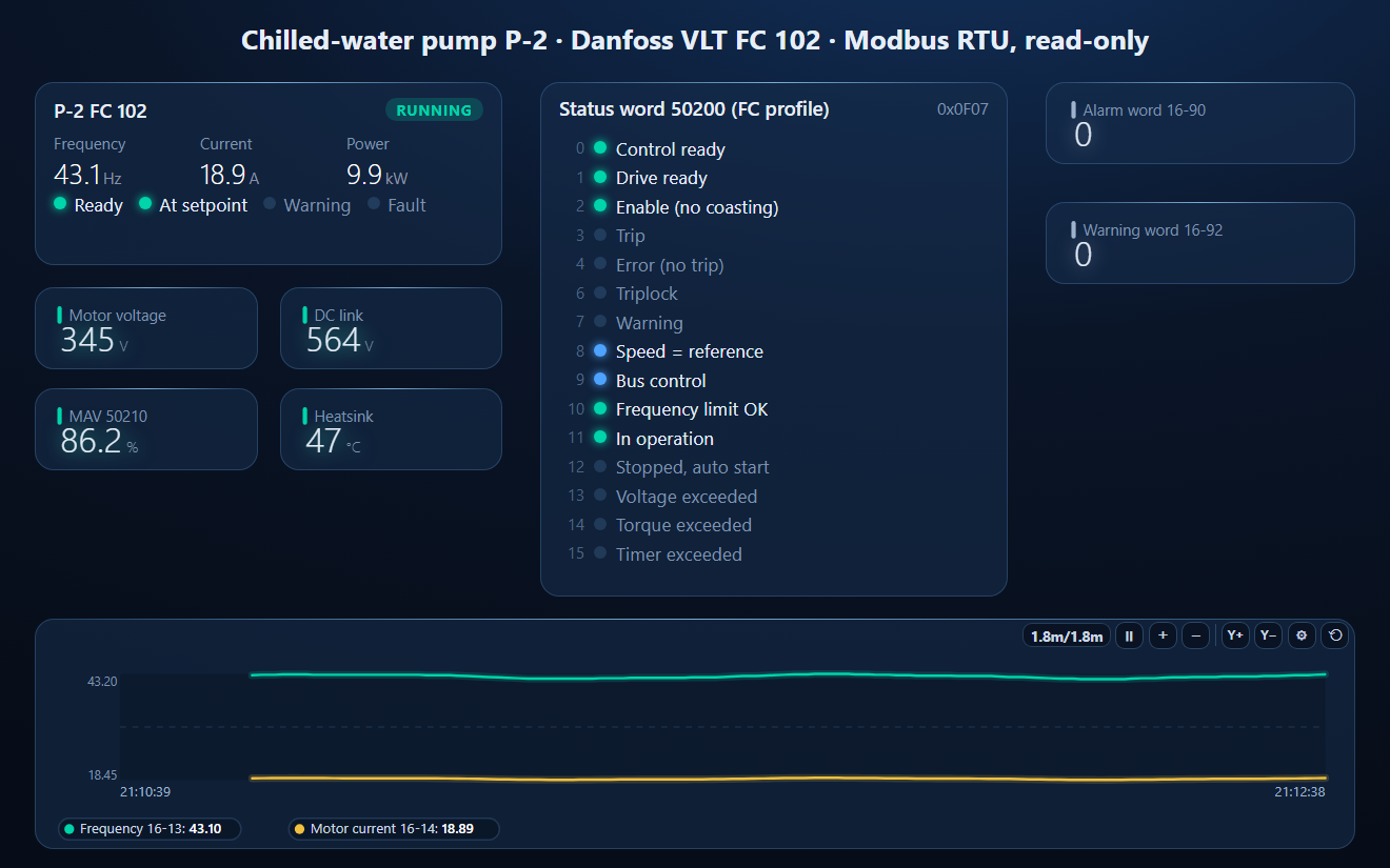
A drive running at its reference under bus control reads 0x0F07.
Common Mistakes
- No answer at all: 8-30 still FC protocol, or changed without a power cycle.
- Values one register off: 16-13 requested at 16130 instead of 16129.
- Frequency 427 instead of 42.7: the conversion index; divide by 10.
- Current or power looks absurd: a 32-bit parameter read as one register, or the words swapped.
- Writes ignored: bit 10 (data valid) is 0, or 8-50 … 8-56 give the digital inputs priority.
- Drive runs on after the master is gone: 8-04 Control Word Timeout Function is Off by default.
- Parameter changes lost after power-off: coil 65 was 0, so they went to RAM only.
Step-by-Step: Reading an FC 102 with ModbusManager
- Set 8-30 = Modbus RTU, 8-31 address, 8-32 baud rate, 8-33 even parity; power the drive off and on.
- Wire terminals 68 / 69, S801 ON at the end of the line.
- In ModbusManager choose RTU with the same baud rate, Even parity, 1 stop bit.
- Read FC03 address 50199, quantity 1: the status word. 0x0F07 is a running drive.
- Open the workspace below for the scaled parameters on a dashboard.
Download a Ready-Made Workspace
- Ten FC03 polls, one per parameter: STW, MAV, 16-13, 16-14, 16-10, 16-12, 16-30, 16-34, 16-90, 16-92
- 10 tags with the wire address, data type and conversion index already applied
- A dashboard: drive faceplate, the FC-profile status word bit by bit, motor voltage, DC link, MAV, heatsink, alarm and warning words and a frequency and current trend
Danfoss_FC102_monitor.json
Danfoss VLT FC 102 / FC 302 read-only workspace. Open via Workspace › Open in ModbusManager Pro.
Try it with ModbusManager Pro
Drive faceplate, status bits, historian and alarms. Free 14-day trial. No credit card. Windows 10/11.
Other drives: ABB ACH580, ABB ACS580, and references across brands in the VFD speed reference guide.
Frequently Asked Questions
How do I enable Modbus RTU on a Danfoss FC 102?
Set 8-30 Protocol to Modbus RTU, 8-31 the address, 8-32 the baud rate and 8-33 parity (even, 1 stop bit by default), then power the drive off and on: the protocol change applies only after a power cycle.
What is the Modbus register of a Danfoss parameter?
Ten times the parameter number: 16-13 Frequency is register 16130, which is address 16129 on the wire. 32-bit parameters use two registers, high word first.
Why does the Danfoss frequency read 10 times too high?
Parameters are transferred as integers. 16-13 has conversion index -1, so 427 means 42.7 Hz. Motor current 16-14 (index -2) is in 0.01 A, power 16-10 in 10 W steps.
Which registers hold the Danfoss control and status word?
Control word 50000, bus reference 50010, status word 50200 and main actual value 50210 (on the wire one less). Reference and actual value are scaled 16384 = 100 %.
Does the FC 302 use the same Modbus registers?
The FC 301/FC 302 programming guide has the same 8-30 Modbus RTU option, baud rates and 16-1x readouts with the same data types and conversion indexes. Check parameters that exist only on one drive in its own guide.
Sources
Danfoss, VLT HVAC Drive FC 102 Design Guide MG11BC02 (06/2014), chapter 8 "RS-485 Installation and Set-up"; VLT HVAC Drive FC 102 Programming Guide, software 7.61, AU430028034214en (2024.10); VLT AutomationDrive FC 301/FC 302 Programming Guide, software 9.5x, AU275636650261en (2024.09). All public at assets.danfoss.com. The guides do not say what the drive answers for a register between two parameters; the workspace avoids those. Tested against a simulator built from these documents, not a physical drive.