Carel pCO Modbus: From Carel Variables to Modbus Addresses (A, I, D and the Threshold)
Carel pCO controllers run thousands of chillers, air handlers and heat pumps — under Carel's name and under the names of the OEMs that build on them. There is no single pCO register list: every application program publishes its own list of supervisor variables, numbered the Carel way (A1, I12, D70). What Carel does define is how those numbers become Modbus addresses. This guide covers that rule, the threshold that moves the integers, the × 10 on analogues, and a worked example with Carel's own Standard Modular Chiller application.
Enable Modbus on the pCO
- Hardware: the BMS port with an RS-485 option card (Modbus RTU), or a pCOWeb card for Modbus TCP.
- Protocol: set in the application — in Carel's Standard Modular Chiller, screen R5 “supervisor protocol” (CAREL by default, change to MODBUS), screen R6 speed (19200 default) and address (1 default). Underneath it is the system variable COM_PROTOCOL_BMS: 3 = Modbus, 30 = Modbus extended.
- Frame: COM_CONFIG — bit 0 = 0 means 2 stop bits, 1 means 1 stop bit; bits 4–5 parity (00 none, 01 even, 10 odd). The application decides what it sets.
- Timing: at 19200 Carel recommends a 1000 ms timeout and 50–200 ms between requests.
The Mapping Rule
| Carel variable | Modbus | Function codes |
|---|---|---|
| Digital D[n] | coil n | 01 / 02 read (same data), 05 / 15 write |
| Analogue A[n] | register n, value × 10, signed | 03 / 04 read (same data), 06 / 16 write |
| Integer I[n] | register Th + n | 03 / 04, 06 / 16 |
The threshold Th depends on the protocol number and the BMS_EXTENSION setting:
| Protocol | BMS_EXTENSION | Th | I[1] is register |
|---|---|---|---|
| 3 (Modbus) | 0 | 128 | 129 |
| 3 (Modbus) | 1 | 208 | 209 |
| 30 (Modbus extended) | — | 5001 | 5002 |
Through a pCOWeb (Modbus TCP, port 502) the layout is digitals = coils 1–2048, analogues = registers 1–5000, integers = registers 5001–10000; pCOWeb talks to the pCO with the Carel protocol or Modbus extended (30), not simple Modbus (3).
Worked Example: Standard Modular Chiller HP
From the supervisor variable list in Carel's application manual (protocol 3, BMS_EXTENSION 0, Th = 128):
| Variable | Modbus | Value |
|---|---|---|
| D1 | coil 1 | Unit on / off |
| D42 | coil 42 | On / off from supervisor (R/W, needs screen R4 enabled) |
| D51 | coil 51 | Mode: 0 chiller, 1 heat pump |
| D57 | coil 57 | Reset alarms (R/W) |
| D70 | coil 70 | General alarm |
| D71 / D77 / D78 / D82 | coils | Antifreeze / evaporator flow switch / high pressure / low pressure |
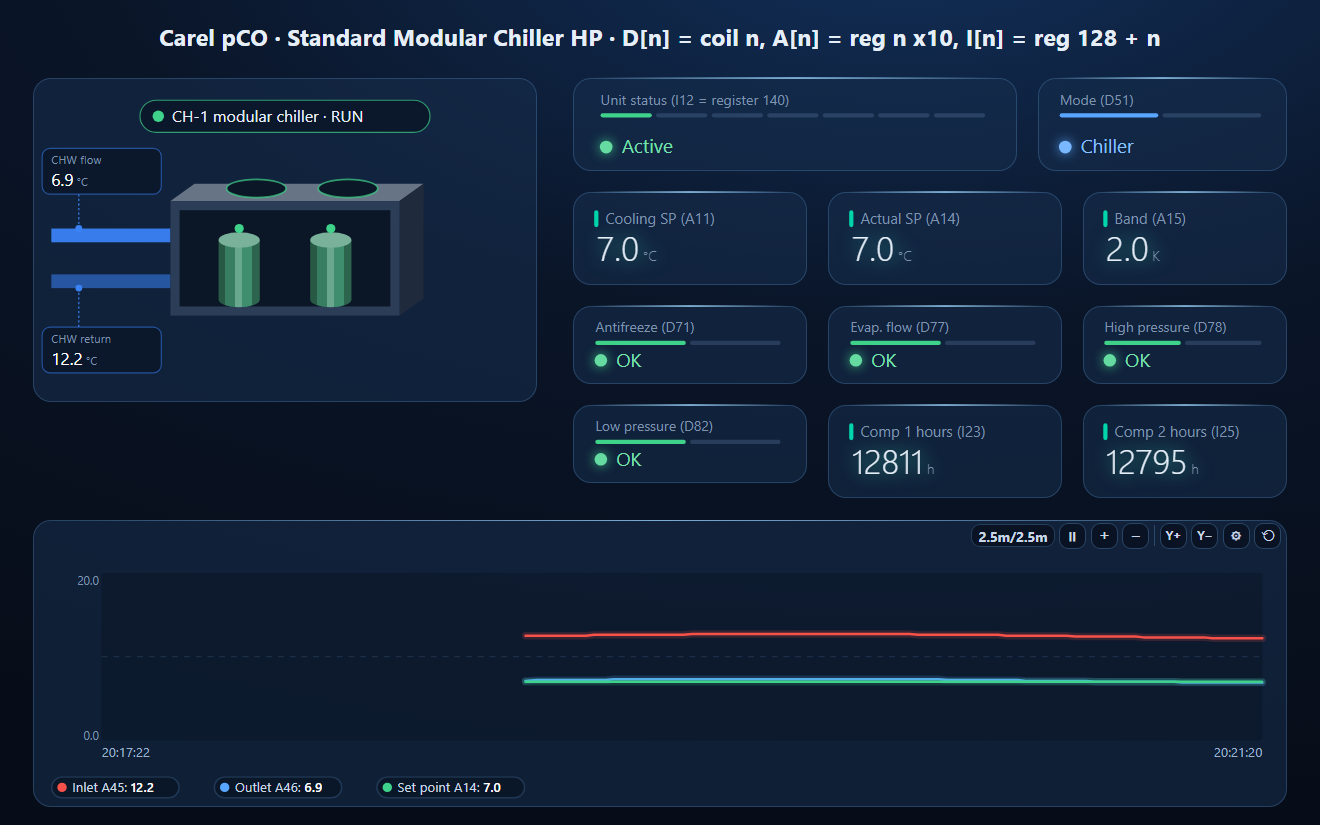
| A11 / A12 | register 11 / 12 | Cooling / heating set point (R/W) × 10 |
| A14 / A15 | register 14 / 15 | Current set point / band × 10 |
| A45 / A46 | register 45 / 46 | Main inlet / outlet water temperature × 10 |
| I12 | register 140 | Unit status: 0 active, 1 off by alarm, 2 off by supervisor, 3 time bands, 4 digital input, 5 keypad, 6 manual |
| I20 / I21 | register 148 / 149 | Main pump hours, high / low word |
| I22…I29 | register 150…157 | Compressor 1–4 hours, high / low word each |
Another application — or an OEM's own program on the same pCO — uses the same numbers for something else. Always work from the supervisor list of the program that runs on your unit.
Common Mistakes
- No answer: the supervisor protocol is still CAREL, or the frame (stop bits / parity) differs.
- Integers read as nonsense: the wrong threshold — 129, 209 or 5002 for I[1] depending on the protocol.
- Every value one off: the n / n + 1 question above.
- Set point 70 °C: analogues are × 10 — 70 is 7.0 °C; −12.0 °C reads −120 (0xFF88).
- On / off ignored: the application only obeys the supervisor after “enable ON/OFF from supervisor” (R4).
- A wrong value accepted: the pCO does not check the range of values written over Modbus.
- A map from another pCO: it belongs to another application.
Step-by-Step: Reading a pCO with ModbusManager
- Set the supervisor protocol to Modbus, note the address and speed, and get the application's supervisor variable list.
- In ModbusManager choose RTU, that speed, the frame, the address.
- Read FC01 from coil 1 for the digitals; FC03 from register 1 for the analogues (÷ 10); FC03 from Th + 1 for the integers.
- Check one set point at n and n + 1. Or open the workspace below if your unit runs the Standard Modular Chiller application.
Download a Ready-Made Workspace
- Four polls for the Standard Modular Chiller HP application: digitals D1–D104 and D182–D183 (FC01), analogues A1–A46 (FC03), integers I12–I29 (FC03 from 140)
- 17 tags: unit on, mode, alarms, set points and water temperatures ÷ 10, unit status, compressor hours
- A dashboard: the chiller element with chilled water out and return and its general alarm, unit status, mode, set points, band, antifreeze, flow and pressure alarms, compressor hours, and a water / set point trend
Carel_pCO_Chiller.json
Carel pCO workspace for the Standard Modular Chiller HP application (Modbus RTU). Open via Workspace › Open in ModbusManager Pro, or from the in-app Device library.
Try it with ModbusManager Pro
Chiller and AHU elements, Structured Text for application-specific decoding, alarms, historian, and MQTT to Home Assistant. Free 14-day trial. No credit card. Windows 10/11.
Your unit's map in a PDF? The register map service turns it into a workspace. Pumps on the same water circuit: Grundfos MAGNA3. All guides: Modbus device guides.
Frequently Asked Questions
Is there a standard Carel pCO Modbus register list?
No. Each pCO application program publishes its own list of supervisor variables. Carel defines only how a variable number becomes a Modbus address: digital D[n] = coil n, analogue A[n] = register n (x 10), integer I[n] = register threshold + n.
What is the integer offset on a Carel pCO?
The threshold depends on the protocol: 128 for Modbus (protocol 3) with BMS_EXTENSION 0, 208 with BMS_EXTENSION 1, and 5001 for Modbus extended (protocol 30). Integer I[1] is then register 129, 209 or 5002.
Why are Carel analogue values ten times too big?
Analogue variables are sent multiplied by 10 as signed 16-bit registers: 70 is 7.0 °C, -120 is -12.0 °C.
Is A1 register 1 or register 2 on a Carel pCO?
Carel's manual says both in different places. Read a variable you know, such as a set point, at n and n + 1, or ask the pCO itself with FC17 Report Slave ID, which returns the first and last address of each variable area.
How do I switch a pCO from the Carel protocol to Modbus?
In the application's supervisor settings (in Carel's Standard Modular Chiller, screen R5) choose Modbus instead of CAREL, then set speed and address (screen R6). The system variable behind it is COM_PROTOCOL_BMS = 3.
Sources
Carel, Modbus protocol for pCO controllers, +030221945 rel. 1.1 (2012); pCOWeb user manual, +030220966 rel. 1.2 (2018); Standard Modular Chiller HP application manual, +030221251 rel. 2.9 (2015), all carel.com. Tested against a simulator built from these documents, not against a physical controller.