Deep Sea DSE7320 Modbus (GenComm): Page × 256 + Offset, Sentinels and Control Keys
The DSE7320 MKII is Deep Sea Electronics' auto-mains-failure (AMF) controller: it watches the mains, starts the generator when the mains fails, transfers the load and back again. On RS-485 it speaks Modbus RTU through DSE's GenComm register standard. GenComm is logical once you see it — addresses are pages of 256, values that cannot be read come back as sentinel numbers instead of errors, and the start / stop / auto buttons are written as a key and its complement.
Connection
- Modbus RTU on RS-485, selected in the module's configuration with the DSE Configuration Suite.
- 8 data bits, no parity, 1 stop bit. GenComm says DSE controllers use 2 stop bits — “the 73xx family is an exception” and always uses 1.
- Function codes: FC03 (1–125 registers) and FC16 (1–123). No FC04, no FC06.
- Address and baud rate are configured in the module and can be read back on page 1 (offset 0 address, offset 2 baud code: 7 = 9600, 9 = 19200, 11 = 38400, 13 = 115200). DSE's documents give no RS-485 defaults; installers report address 10. The RS-232 port is fixed at address 10, 8N1.
Page × 256 + Offset
GenComm groups registers in pages of 256: register address = page × 256 + offset, the wire address starting at 0. Control mode is page 3 offset 4 = 772; battery voltage is page 4 offset 5 = 1029; generator L1-N is page 4 offset 8 = 1032. A tool that numbers 4xxxx from 1 needs 41033 for the last one. 32-bit values are most significant word first, always at an even address, and must be read in one request.
Key Registers
| Page / offset | Address | Value | Scale |
|---|---|---|---|
| 3 / 4 | 772 | Control mode: 0 stop, 1 auto, 2 manual, 3 test on load, 4 auto with manual restore, 6 test off load, 7 off | — |
| 3 / 6 | 774 | Flags: 13/16 shutdown alarm, 12/16 electrical trip, 11/16 warning, 14/16 control unit failure | bits |
| 4 / 0–3 | 1024–1027 | Oil pressure, coolant temperature, oil temperature, fuel level | kPa, °C, °C, % |
| 4 / 5, 6, 7 | 1029–1031 | Battery voltage, engine speed, generator frequency | 0.1 V, rpm, 0.1 Hz |
| 4 / 8–13 | 1032–1037 | Generator L1 / L2 / L3-N voltage (U32) | 0.1 V |
| 4 / 20–25 | 1044–1049 | Generator L1 / L2 / L3 current (U32) | 0.1 A |
| 4 / 28–33 | 1052–1057 | Generator L1 / L2 / L3 power (S32) | W |
| 4 / 35, 36–41 | 1059, 1060–1065 | Mains frequency, mains L-N voltages | 0.1 Hz, 0.1 V |
| 6 / 0–1 | 1536–1537 | Generator total power (S32) | W |
| 6 / 21, 22 | 1557, 1558 | Average power factor, % of full power | 0.01, 0.1 % |
| 7 / 6–7, 8–9, 16–17 | 1798, 1800, 1808 | Engine run time, generator kWh, number of starts (U32) | s, 0.1 kWh, — |
| 154 / 1… | 39425… | Named alarms, four 4-bit codes per register | codes |
Sentinels Instead of Errors
A value the controller cannot give comes back as data, not as an exception: 0xFFFF (signed 0x7FFF) unimplemented — mains currents without mains CTs, for example — 0xFFFE over range, 0xFFFD under range, 0xFFFC transducer fault, 0xFFFB bad data. 32-bit values use 0xFFFFFFFF / 0x7FFFFFFF. Filter them before a value goes on a trend or into an alarm.
Named Alarms (Page 154)
Each register holds four alarms as 4-bit codes, highest nibble first: offset 1 emergency stop, low oil pressure, high coolant temperature, low coolant temperature; offset 2 under speed, over speed, generator under / over frequency; offset 3 generator low / high voltage, battery low / high voltage; and so on. Codes: 0 disabled, 1 not active, 2 warning, 3 shutdown, 4 electrical trip, 5 controlled shutdown, 15 unimplemented. A healthy controller reads 0x1111.
Control Keys: Key Plus Complement
The buttons are written to page 16: the system control key to offset 8 (address 4104) and its ones' complement to offset 9 (4105), in one FC16 write. Keys are 35700 + function: 35700 stop, 35701 auto, 35702 manual, 35703 test on load, 35705 start, 35708 transfer to generator, 35709 transfer to mains, 35734 reset alarms. GenComm's own example: auto = 35701 (0x8B75), complement 29834 (0x748A). FC06 is not supported, and a key without its complement is ignored.
Common Mistakes
- No answer: Modbus not selected in the module configuration, 2 stop bits on a 73xx, or the wrong address.
- Values off by one register: the 4xxxx / 1-based question — GenComm addresses start at 0.
- A 32-bit value that jumps: its two registers read in two requests.
- 6553.5 V on the mains: 0xFFFF, unimplemented — not a reading.
- Start / stop does nothing: FC06 used, or the key written without its complement.
Step-by-Step: Reading a DSE7320 with ModbusManager
- Select Modbus RTU on the RS-485 port in the DSE Configuration Suite and note the address and baud rate.
- In ModbusManager choose RTU, that baud rate, no parity, 1 stop bit, the address.
- Read FC03 from 772, quantity 3: control mode and flags.
- Read FC03 from 1024, quantity 42: engine, generator and mains values. Or open the workspace below.
Download a Ready-Made Workspace
- Five FC03 polls: page 3 (control mode, flags), page 4 (engine, generator, mains), page 6 (totals, PF), page 7 (run time, kWh, starts), page 154 (named alarms)
- 29 register tags with GenComm's scaling and 32-bit values high word first, plus a script that decodes the alarm flags, decides which side is on load and converts run time to hours
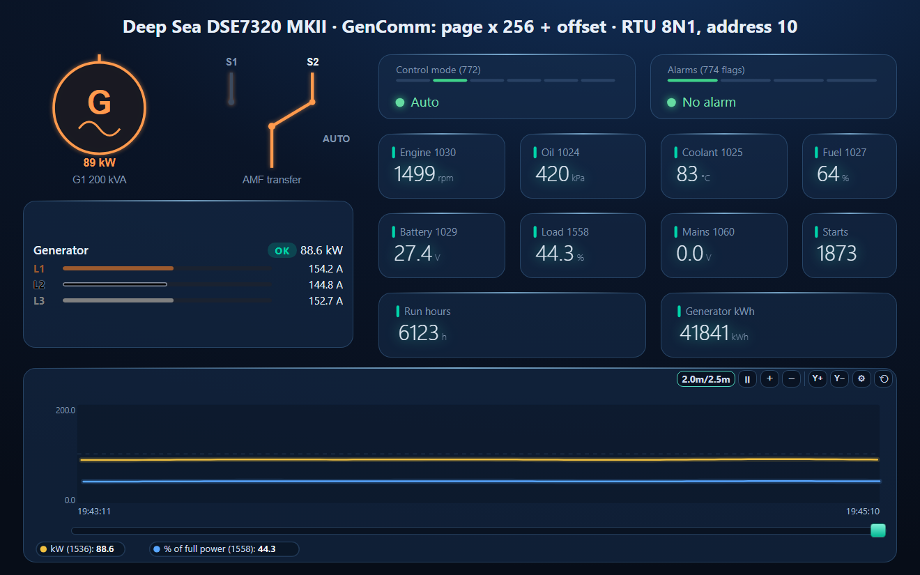
- A dashboard: the generator and transfer-switch elements, the generator as a three-phase meter, control mode, alarms, engine speed, oil, coolant, fuel, battery, load, mains voltage, starts, run hours, kWh, and a load trend
DeepSea_DSE7320.json
Deep Sea DSE7320 MKII AMF controller workspace (Modbus RTU, GenComm). Open via Workspace › Open in ModbusManager Pro, or from the in-app Device library.
Try it with ModbusManager Pro
Generator and transfer-switch elements, alarms on GenComm flags, historian for run hours and fuel, and MQTT to Home Assistant. Free 14-day trial. No credit card. Windows 10/11.
The incomer next to the generator: Socomec DIRIS A-40 or Janitza UMG 96-PA. All guides: Modbus device guides.
Frequently Asked Questions
How do I calculate a DSE GenComm Modbus address?
Register address = page x 256 + offset, starting at 0 on the wire. Control mode is page 3 offset 4 = 772, battery voltage page 4 offset 5 = 1029, generator L1-N voltage page 4 offset 8 = 1032.
What serial settings does a DSE7320 use?
8 data bits, no parity, 1 stop bit - the 73xx family uses 1 stop bit where other DSE controllers use 2. The address and baud rate are set in the module configuration and can be read back on page 1.
Why does a DSE register read 65535?
GenComm returns sentinels instead of exceptions: 0xFFFF (signed 0x7FFF) means the value is not implemented, 0xFFFE over range, 0xFFFD under range, 0xFFFC transducer fault.
How do I start or stop a DSE7320 over Modbus?
Write the system control key to address 4104 and its ones' complement to 4105 in one FC16 message: 35701 auto, 35700 stop, 35705 start. FC06 is not supported.
Where can I get the DSE GenComm register list?
DSE supplies the full GenComm specification on request from support@deepseaplc.com, quoting the controller's serial number.
Sources
Deep Sea Electronics, GenComm standard for use with generating set control equipment (DSE7310 GenComm, 2019), as hosted by a DSE distributor; DSE7310 MKII & DSE7320 MKII installation instructions 053-181. The RS-485 default address is reported by installers, not documented by DSE. Tested against a simulator built from GenComm, not against a physical controller.